The Relay & Sensor Board is an optional accessory for the eddi, designed to enhance functionality and flexibility for different wiring configurations. Below, we provide an in-depth guide on its features, installation process, and configuration options.
Overview of the Relay & Sensor Board
The Relay & Sensor Board expands the eddi's capabilities by adding:
-
Two independent multifunction relays (16 Amp each):
These can be configured independently or as a pair for various functions.
-
eSense Input:
An isolated 230V detection input, ideal for economy tariff sensing or similar applications.
-
Two temperature sensor inputs:
Compatible with PT1000 sensors for accurate temperature monitoring.
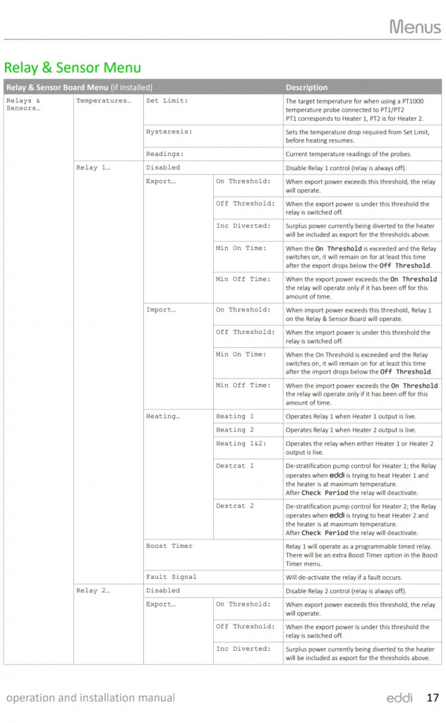
Relay Functions
Each relay can be configured for the following operational modes:
-
Export Threshold: Activates when a specific export level is reached.
-
Import Threshold: Triggers based on import conditions.
-
Operate When Heating: Designed to activate during heating operations.
-
De-stratification Pump Control: Ideal for managing thermal storage systems.
-
Timed Operation: Configures the relay to activate for specific time intervals.
-
Fault Signal for BMS Systems: Used for signalling issues to a Building Management System (BMS).
Note: It is often possible to split a 3-phase heating element into three individual elements by removing the linking connectors.
|
Installing the Relay & Sensor Board
What You’ll Need:
- myenergi Relay & Sensor Board
- The three plastic spacers included in the board package
- Provided flexible ribbon cable
Step-by-Step Instructions:
-
Preparation:
- Ensure the eddi is powered off and disconnected from the mains supply before starting installation
- Locate the eddi's main circuit board by opening the device enclosure.
-
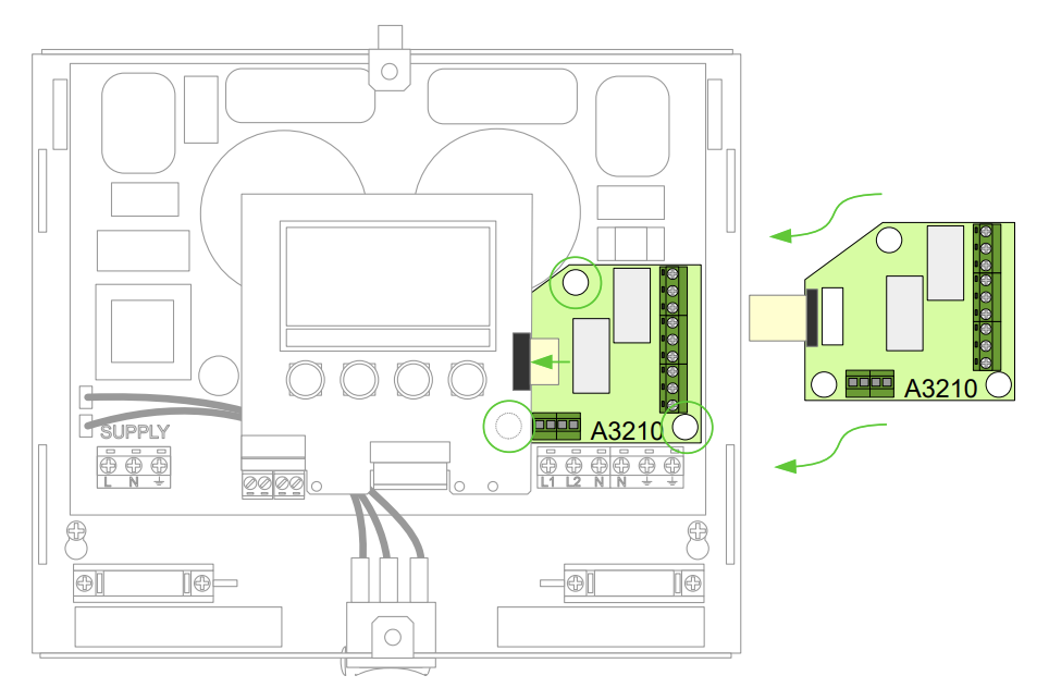
Mounting the Board:
- Position the Relay & Sensor Board over the designated connectors on the eddi’s main circuit board.
- Secure the board using the three plastic spacers provided.
-
Connecting the Ribbon Cable:
- Plug one end of the flexible ribbon cable into the black connector on the Relay & Sensor Board.
- Insert the other end into the black connector located on the right-hand side of the display on the top eddi circuit board.
-
Verification:
- Ensure all connections are secure and check that the board is correctly aligned with the mounting points.
|
Configuration and Application Examples & Menus
Refer to the Application Examples section in our help centre here for practical wiring configurations and use cases. These examples demonstrate how to utilise the Relay & Sensor Board effectively for specific applications, such as economy tariffs, de-stratification pumps, and more.
|
Image Reference
|