Introduction
For single-phase and three-phase systems, the installation of CTs differs slightly:
-
-
Single-phase zappi or eddi:
- Requires a harvi to measure the current on all three phases.
- It is not possible to connect three CTs from different phases directly to a single-phase zappi.
-
Three-phase zappi:
- The three CTs can be directly wired to the zappi.
Key Considerations
- The CTs must be clipped onto the correct cables:
-
CT1 on Phase 1, CT2 on Phase 2, and CT3 on Phase 3.
- Ensure the arrow on each CT points towards the consumer unit or fuse board.
- The phase rotation setting on the zappi must align with the three-phase wiring configuration.
- The simplest and default wiring setup for zappi is:
- L1 → Terminal 1
- L2 → Terminal 2
- L3 → Terminal 3
- Neutral and Earth appropriately connected.
More information about phase rotation settings is covered in a separate article.
-
|
Checking the CTs
To verify the CTs are correctly installed, follow these steps:
-
Initial Setup
- Turn off any local generation sources (e.g., PV or wind).
- Ensure the household load is sufficient, drawing at least 1A per phase.
-
Access CT Readings
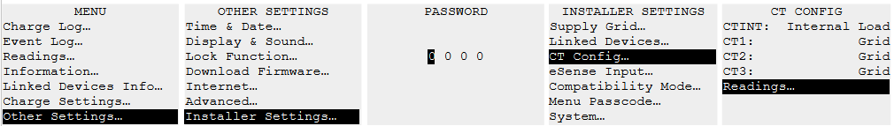
- For CTs directly connected to zappi:
- Navigate to Other Settings → Installer Settings → CT Config → Readings.
 - For CTs connected via a harvi:
- Navigate to Settings → Installer Settings → Linked Devices → Devices → harvi
-
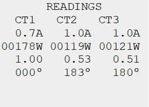
Evaluate Readings
- Each CT should display a positive power value with a power factor close to 1.0 (at least 0.9).
- If a CT shows a power factor around 0.5, it is likely clipped onto the wrong phase.
-
|
Identifying and Correcting Misaligned CTs
If it is unclear which CT is misaligned, use the following method:
- Clip all CTs around the same wire.
- Check the CT readings:
- One CT will show a power factor close to 1.0 (correct phase).
- The others will show power factors near 0.5 (incorrect phases).
- Relocate the CTs as follows:
-
Step 1:
- Identify the CT with a power factor of 1.0.
- Leave it on its current phase.
-
Step 2:
- Move the other two CTs to a different wire.
- Check the readings again.
- One will show a power factor close to 1.0 (correct phase), and the other will show a power factor near 0.5.
-
Step 3:
- Move the final CT to the remaining wire.
- Confirm the readings.
- Repeat until all CTs are correctly aligned with their respective phases.
|
Final Validation
Once all CTs are correctly installed:
- The power readings should align with expected values.
- All CTs should show a positive power value with a power factor close to 1.0.
If you encounter issues or require further assistance, contact the myenergi Support Team for guidance.